| Author |
Message |
Boneheimer

az supporter


Joined: Wed Sep 15, 2010 7:50 am Posts: 228 Location: Cairns
Vehicle: 91 Tin Top, 04 Jimny

|
 Posted: Tue Jan 17, 2012 5:21 am |
|

Have been doing a little bit of research, and looking for a wiring diagram for a vitara in order to splice looms.
I have checked with my local suzuki dealership and they're too busy to help, I also asked google, but probably the wrong thing, so....
I was wondering when the switch over date is for the vitara wiring diagram in the 95-96 period, as all the wiring diagrams I've seen are for either 91-95 models, or 96-98.
So basically my question is which wiring diagram should I be using?
( I ask this because it's not always so simple as build date, eg. my moto is an 09 build, but a 2010 model. )
Details; Vitara
Type: E-TA02C - (SE416?)
Engine: G16B - 16 valve
Build date: November 95
Also the distributor is the 7 pin variant if this helps
Cheers 
Last edited by Boneheimer on Tue Jan 17, 2012 10:57 pm, edited 1 time in total.
|
|
|
|
|
royce
omnipotent being

Joined: Sun Jun 11, 2006 11:30 pm Posts: 17216 Location: Pluto
|
Posted: Tue Jan 17, 2012 6:29 am |
|
|
7 pin dissy and 3 wire afm I would go with the later version
but easiest to look at both looms and compare pinouts of key things like the dissy and ecu powers
|
|
|
|
|
Boneheimer
az supporter
Joined: Wed Sep 15, 2010 7:50 am Posts: 228 Location: Cairns
Vehicle: 91 Tin Top, 04 Jimny
|
Posted: Tue Jan 17, 2012 7:53 am |
|
royce wrote: 7 pin dissy and 3 wire afm I would go with the later version
This is what I was thinking, but will compare the pinouts as you said, thanks royce
|
|
|
|
|
Boneheimer
az supporter
Joined: Wed Sep 15, 2010 7:50 am Posts: 228 Location: Cairns
Vehicle: 91 Tin Top, 04 Jimny
|
Posted: Tue Jan 17, 2012 11:04 pm |
|
Ok, so based on the wires I traced i'm pretty sure that I'm running the 96+ configuration.
I had a look at my ecu pinout by taking the cover off, and this is what I found:
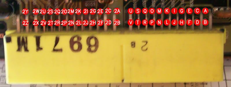
Which is a completely different system to that on the best wiring diagram I could find HERE
If anyone knows how these two systems relate, or if there is a better pinout diagram available please let me know, as I ran out of welding gas and can't get any more today  leaving wiring as the only thing I can do for now...
|
|
|
|
|
JrZook

Joined: Tue Aug 08, 2006 11:30 pm Posts: 5517 Location: Holland Park
Vehicle: Awesome!!
|
Posted: Tue Jan 17, 2012 11:11 pm |
|
|
Do you have both looms? Where abouts in Cairns are ya?
_________________ Lil Foot!
http://tiny.cc/gtsw1
|
|
|
|
|
Boneheimer
az supporter
Joined: Wed Sep 15, 2010 7:50 am Posts: 228 Location: Cairns
Vehicle: 91 Tin Top, 04 Jimny
|
Posted: Tue Jan 17, 2012 11:17 pm |
|
|
Yep, both out of the cars, I'm out at Clifton beach
|
|
|
|
|
Boneheimer
az supporter
Joined: Wed Sep 15, 2010 7:50 am Posts: 228 Location: Cairns
Vehicle: 91 Tin Top, 04 Jimny
|
Posted: Wed Jan 18, 2012 4:32 am |
|
Ok, so I've been looking further, and still have NFI how to do this.
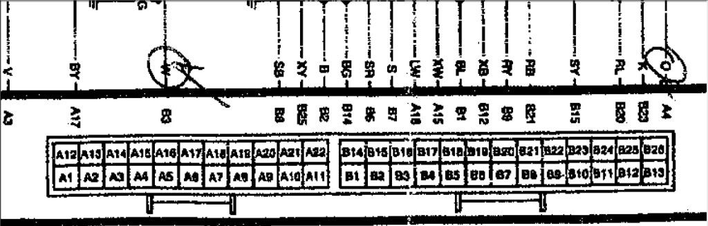
I have done a little bit of trimming on the wiring diagram itself, to leave what I think is vital for a M/T vitara.
Even with cutting all of the auto crap out of the diagram i'm still at a loss to how the ecu and diagram pinouts relate.
For example the orange wire from the distributor goes to "B4" on the diagram, but IRL it goes to the pin marked "G" on the ecu. 
I'll attach the updated wiring diagram as well, it's a WIP.
You do not have the required permissions to view the files attached to this post.
Last edited by Boneheimer on Wed Jan 18, 2012 7:59 am, edited 1 time in total.
|
|
|
|
|
royce
omnipotent being
Joined: Sun Jun 11, 2006 11:30 pm Posts: 17216 Location: Pluto
|
Posted: Wed Jan 18, 2012 5:06 am |
|
|
it will make more sense if you use wire colours and focus only on any circuit that isnt between teh ECU and something you can plug into teh engine
|
|
|
|
|
Boneheimer
az supporter
Joined: Wed Sep 15, 2010 7:50 am Posts: 228 Location: Cairns
Vehicle: 91 Tin Top, 04 Jimny
|
Posted: Wed Jan 18, 2012 8:01 am |
|
|
The majority of the wire colours don't match up, might have to go back to local suzuki dealer and hassle them for the correct diagram...
|
|
|
|
|
Rhinoman
Joined: Mon May 16, 2011 7:03 pm Posts: 686 Location: Brinkworth, England
|
Posted: Wed Jan 18, 2012 8:12 pm |
|
Boneheimer wrote: Which is a completely different system to that on the best wiring diagram I could find HEREI'm pretty sure that is a US diagram for an OBD2 ECU with four connectors. Yours is OBD1, I don't recognise the number on the connector, what part number is the ECU? do you have an immobiliser? the pin out is different if you do. The connector pin numbers are usually all messed up on these ECUs, I've no idea why. The real pin numbers are molded in the mating half of the connector.
On most wiring diagrams looking staright into the ECU connector, right hand connector is A1 is top right, A11 top left, A12 is bottom right, A22 bottom left.
Left hand connector, follows the same pattern with B1 top right and B26 bottom left.
I'm currently hacking a 16V ECU - one of my tasks for tomorrow is to scan the schematic. I'll post a link up when I've done that. Out of interest can you please post a picture of the complete PCB? Thanks.
Edit: on the shematic I have A4 is the orange wire which tallies witth what you have.
_________________
2000 Suzuki Vitara 1.6 8V
1986 Suzuki SJ413K
|
|
|
|
|
Boneheimer
az supporter
Joined: Wed Sep 15, 2010 7:50 am Posts: 228 Location: Cairns
Vehicle: 91 Tin Top, 04 Jimny
|
Posted: Wed Jan 18, 2012 9:54 pm |
|
Rhinoman wrote: I'm pretty sure that is a US diagram for an OBD2 ECU with four connectors. Yours is OBD1 This is correct, there was only one O2 sensor on the donor Vit. Rhinoman wrote: What part number is the ECU? I'm not sure where the part number is? The serial is JE331B761B - Mitsubishi type. Rhinoman wrote: Do you have an immobiliser? Unsure Rhinoman wrote: The real pin numbers are molded in the mating half of the connector. Neither the male or female plugs have any numbers molded into them, the circuit board has eight pin ID's printed on it, in the image above you can see the pin numbers derived from those. You can see a few of the actual pin numbers in the image below. Rhinoman wrote: Out of interest can you please post a picture of the complete PCB? Thanks.
By PCB you mean printed circuit board? If so I tried to keep the image as large as possible for detail.

Hopefully this helps
|
|
|
|
|
Rhinoman
Joined: Mon May 16, 2011 7:03 pm Posts: 686 Location: Brinkworth, England
|
Posted: Thu Jan 19, 2012 7:11 am |
|
The ECU has the chip fitted for an immobiliser but that may not mean that there is one. The immo ECUs have the fuel pump wire on a different pin to stop you swapping in a non-immo ECU so if you check for that wire that will tell you which one you have.
The other change between ECUS is the EGR valve which can be either a vacuum operated version or a stepper motor, that one is pretty obvious when you check the EGR itself.
Schematic is now here:
http://www.rhinopower.org/repairs/schem ... ematic.pdf
http://www.rhinopower.org/repairs/schem ... te_key.pdf
Thanks for the pic, it looks similar to the 58B90 that we got here. The part number is on the case it will be 33920-something
Cheers
James
_________________
2000 Suzuki Vitara 1.6 8V
1986 Suzuki SJ413K
|
|
|
|
|
Boneheimer
az supporter
Joined: Wed Sep 15, 2010 7:50 am Posts: 228 Location: Cairns
Vehicle: 91 Tin Top, 04 Jimny
|
Posted: Thu Jan 19, 2012 7:47 am |
|
Rhinoman wrote: The part number is on the case it will be 33920-something
Here's a pic of the case sticker with the part number:

Thanks for those diagrams and keys, I'll have a look at them tonight, might also have a look on your rhino power forum, looks like it has a lot of useful info.
|
|
|
|
|
Boneheimer
az supporter
Joined: Wed Sep 15, 2010 7:50 am Posts: 228 Location: Cairns
Vehicle: 91 Tin Top, 04 Jimny
|
Posted: Thu Jan 19, 2012 10:08 am |
|
Just putting this here to keep track of my thoughts and remind me what I have to do tomorrow 
Most of the wires from Rhinoman's diagram match up, but I have yet to trace wires to their respective components to double check.
Things that didn't match up:
A2 - Colour mismatch - trace [Engine start switch]
A5* - Wire present, when diagram shows blank - trace
A17 - Colour mismatch - trace [Diag. switch terminal?]
A21* - No wire, when diagram indicates wire [Fuel pump relay]
B1 - Colour mismatch - trace [Ground]
B2 - Colour mismatch - trace [Ground]
B3 - Colour not indicated on diagram, assume black?
B7 - Colour mismatch - trace [TP Sensor]
B16 - Colour mismatch - trace [Data link connector]
B17 - Diagram shows EGR stepper motor wire, if no stepper motor then WTF is this wire doing here? - trace
B19 - Wire present, when diagram shows blank - trace
B20 - Colour not indicated on diagram, assume black?
B22* - No wire, when diagram indicates wire, also colour not indicated on diagram, assume black? [Ignition switch]
* = terminal which has been newly added or modified to installation of immobiliser control system
Edit: ^^ I'm guessing this is what Rhinoman was talking about above with the immobiliser chip
You do not have the required permissions to view the files attached to this post.
Last edited by Boneheimer on Thu Jan 19, 2012 11:43 am, edited 1 time in total.
|
|
|
|
|
tazmanier
Joined: Fri Jun 26, 2009 11:30 pm Posts: 47 Location: gerringong
Vehicle: 89 SWB zuke
|
Posted: Thu Jan 19, 2012 11:24 am |
|
Hey mate, this is a screen shot of an PDF that someone has scanned from a haynes or some other manual. so far from ideal I know but If you send me an e-mail I will send the PDF at least. Its for the latter model Vit. Worked a treat for mine and I have an engine from a 96 Vit. dont know what month.
The kicker with this diagram (and mabey yours) is its labled as if you are looking at the back of the plug ie. the plugs are pluged in to the ECU and your looking at it from the back. Took me 6 months of fumblin through it to work that out. But once I did it all matched up apart from 1 or 2 colour mismatches.
-TAZ
|
|
|
|
|
Rhinoman
Joined: Mon May 16, 2011 7:03 pm Posts: 686 Location: Brinkworth, England
|
Posted: Thu Jan 19, 2012 11:55 am |
|
That diagram is from here:
http://www.rhinopower.org/repairs/schem ... m-g16b.pdf
I didn't post it originally because I find it so difficult to use for the reason that you stated above. I keep meaning to produce a pinout sheet for it.
From your list of problems I suspect Taz is correct and the pinout is an early pin out (59B series not 57B) although there are a few differences on the PCB.
The list of difference for the later 16V immo and non-immo didn't scan properly earlier but its here:
http://www.rhinopower.org/repairs/schem ... hanges.pdf
_________________
2000 Suzuki Vitara 1.6 8V
1986 Suzuki SJ413K
|
|
|
|
|
zayzuki
newbie
Joined: Sun Sep 26, 2021 10:37 pm Posts: 2
Vehicle: vitara
|
Posted: Mon Oct 04, 2021 11:29 am |
|
|
anyone know how to connect the tcc for 57b series ecu am seeing 2 wire on the diagram and 3 wire on the transmission
|
|
|
|
|
|


