| Author |
Message |
vl2dy4

az supporter


Joined: Wed Feb 16, 2011 8:40 am Posts: 424 Location: Australind WA

|
 Posted: Sat Apr 23, 2011 9:21 pm |
|
|
What voltage should be getting to the headlights?
when i measure off the Battery terminals i'm getting 14.8 volts approx, and at the headlights i'm getting 13.6 volts approx, so that means that i have a 1.2volt drop through the wiring, but will the extra 1.2 volts really make a difference?
I have also just upgraded my Alternator to the Mitsubishi 110amp ford alternator.
Cheers
Conrad
_________________
I HATE CYCLISTS!!!
|
|
|
|
|
Scrawny
I live here!

Joined: Tue Jan 29, 2008 10:30 pm Posts: 10528 Location: Brissie
Vehicle: Popemobile
|
Posted: Sat Apr 23, 2011 10:02 pm |
|
14.8v is a bit much at the battery 
|
|
|
|
|
whincup
az supporter

Joined: Sat Apr 17, 2010 11:30 pm Posts: 1588 Location: Gracemere, QLD
Vehicle: '94 suzuki maruti
|
Posted: Sat Apr 23, 2011 10:04 pm |
|
vl2dy4 wrote: will the extra 1.2 volts really make a difference? this is taken straight from http://www.danielsternlighting.com/tech ... elays.htmlQuote: When operating voltage drops to 95 percent (12.54v), headlamp bulbs produce only 83 percent of their rated light output. When voltage drops to 90 percent (11.88v), bulb output is only 67 percent of what it should be. And when voltage drops to 85 percent (11.22v), bulb output is a paltry 53 percent of normal
i only assume this is true, but it seems right to me after seeing the difference between stock and relayed headlights
|
|
|
|
|
royce
omnipotent being
Joined: Sun Jun 11, 2006 11:30 pm Posts: 17216 Location: Pluto
|
Posted: Mon Apr 25, 2011 8:59 am |
|
Made a loom for a Sierra today  drops 0.2v on high beam
You do not have the required permissions to view the files attached to this post.
|
|
|
|
|
Moag
az supporter

Joined: Thu Mar 04, 2010 10:30 pm Posts: 411 Location: Kununurra WA ^ Top End
Vehicle: 2001 Jimny M13A
|
Posted: Mon Apr 25, 2011 9:05 am |
|
That's a thing of beauty Royce... 

|
|
|
|
|
royce
omnipotent being
Joined: Sun Jun 11, 2006 11:30 pm Posts: 17216 Location: Pluto
|
Posted: Mon Apr 25, 2011 9:09 am |
|
|
This is why you dont stick massive wattage globes in and why if you dont understand electricity, STAY THE HELL AWAY FROM IT
This sierra had burnt the high beam side in the dipper switch, for some reason the tard that owned it before thought it was a good idea to tap the drivers side to the passenger side but crossed and the high and low beam wire in teh process
You do not have the required permissions to view the files attached to this post.
|
|
|
|
|
Moag
az supporter
Joined: Thu Mar 04, 2010 10:30 pm Posts: 411 Location: Kununurra WA ^ Top End
Vehicle: 2001 Jimny M13A
|
Posted: Mon Apr 25, 2011 9:17 am |
|
royce wrote: This is why you dont stick massive wattage globes in and why if you dont understand electricity, STAY THE HELL AWAY FROM IT
This sierra had burnt the high beam side in the dipper switch, for some reason the tard that owned it before thought it was a good idea to tap the drivers side to the passenger side but crossed and the high and low beam wire in teh process
Not to mention what's its doing to your dimmer switch with high wattage globes with stock wiring.

|
|
|
|
|
royce
omnipotent being
Joined: Sun Jun 11, 2006 11:30 pm Posts: 17216 Location: Pluto
|
Posted: Mon Apr 25, 2011 9:21 am |
|
Moag wrote: royce wrote: This is why you dont stick massive wattage globes in and why if you dont understand electricity, STAY THE HELL AWAY FROM IT
This sierra had burnt the high beam side in the dipper switch, for some reason the tard that owned it before thought it was a good idea to tap the drivers side to the passenger side but crossed and the high and low beam wire in teh process Not to mention what's its doing to your dimmer switch with high wattage globes with stock wiring. hehe yeah, it wasnt working on high beam but worked on the passing flash (hehe passing, in a sierra)
The plastic housing had melted around the little arm things and flowed between the contacts and set again so it didnt work 
|
|
|
|
|
truongski
az supporter

Joined: Tue Sep 21, 2010 4:59 am Posts: 164 Location: Brisbane South
Vehicle: SWB Vit & LWB GV
|
Posted: Mon Apr 25, 2011 9:37 am |
|
|
Royce,
That loom looks awesome. Looks like I'll have to get some corrugated tubing. Are you using relay holders? Where did you get the fuse holder from? Is the black cable from the fuse holder the postive from the battery?
Cheers.
_________________
stock as a rock
|
|
|
|
|
royce
omnipotent being
Joined: Sun Jun 11, 2006 11:30 pm Posts: 17216 Location: Pluto
|
Posted: Mon Apr 25, 2011 9:43 am |
|
|
nah those ones they are just a molded plug for the relays, the next ones I do will have a screw in place relay holder, fuse holder is ebay, black cable goes on up the loom a bit to teh heater cable grommet for the switch for the spotties in the cab, red cable poking out a little way down in teh fat stuff is the power from the battery
|
|
|
|
|
truongski
az supporter
Joined: Tue Sep 21, 2010 4:59 am Posts: 164 Location: Brisbane South
Vehicle: SWB Vit & LWB GV
|
Posted: Mon Apr 25, 2011 9:47 am |
|
|
Looking good. Definitely not your first time. Thanks for the advice.
_________________
stock as a rock
|
|
|
|
|
fordem
Joined: Mon Apr 19, 2010 11:30 pm Posts: 2648 Location: Georgetown, Guyana
Vehicle: JB420, APK416, A6G415, A6N415
|
Posted: Mon Apr 25, 2011 2:52 pm |
|
Moag wrote: That's a thing of beauty Royce... X2 - it's also nice to know I'm not the only person who works on the floor
|
|
|
|
|
steak_knife
az supporter

Joined: Fri May 22, 2009 11:30 pm Posts: 21335 Location: Smart Ass Island
|
Posted: Mon Apr 25, 2011 8:36 pm |
|
fordem wrote: Moag wrote: That's a thing of beauty Royce... X2 - it's also nice to know I'm not the only person who works on the floor I call it the "big shelf"....
_________________
I used to be indecisive,
now I'm not so sure.....
|
|
|
|
|
royce
omnipotent being
Joined: Sun Jun 11, 2006 11:30 pm Posts: 17216 Location: Pluto
|
Posted: Tue Apr 26, 2011 6:30 am |
|
Made one for the vit today, tapping off the stock headlight fuses underbonnet for power, it drops 0.4 total, better than 1.5
though it seems my expensive fuse panel for the dual battery stuff is up the shit now so ill have to replace it next 
|
|
|
|
|
Marked
az supporter

Joined: Wed Feb 02, 2011 11:56 pm Posts: 580 Location: Perth
Vehicle: Suzuki Grand Vitata 2006
|
Posted: Wed May 25, 2011 5:42 am |
|
Thanks for the diagram, very helpful. This saved me a bundle as I would have had to go to auto electrician. This site is such an amazing resource, so thanks Royce! I wondered if the 2006 GV was the same, and they are.

One difficulty I had was finding a good firewall entry. (No problem on my old Vitara). So I had to unbolt the fuse box on the drivers side engine bay to get to the bonnet cable so I could pass wires through.
Also, I dont know what the deal with the three prong is on your diagram, is that low and high beam? I think so.
On the 2006 there is just two prongs because the high and low beam are separate. I used tap joiners to wire in the relay to the two wires coming out of high beam.

I also managed to fit a nice switch, rather than the crappy roller one they give you.


|
|
|
|
|
Ben_Sierra
az supporter
Joined: Wed Sep 30, 2009 11:30 pm Posts: 4472 Location: Perth
|
Posted: Wed May 25, 2011 6:58 am |
|
vl2dy4 wrote: What voltage should be getting to the headlights?
when i measure off the Battery terminals i'm getting 14.8 volts approx, and at the headlights i'm getting 13.6 volts approx, so that means that i have a 1.2volt drop through the wiring, but will the extra 1.2 volts really make a difference?
I have also just upgraded my Alternator to the Mitsubishi 110amp ford alternator.
Cheers
Conrad
Well, power delivered to the globes is proportional to the voltage squared, so assuming a nominal resistance of 1, your looking at about 16% more power delivered at 14.8 volts than at 13.6 volts... _________________ I want my old sig back 
|
|
|
|
|
monley
az supporter
Joined: Wed Nov 24, 2010 7:58 am Posts: 11092 Location: Mandurah.W.A.
Vehicle: 84 LWB NT
|
Posted: Fri Jun 24, 2011 2:27 pm |
|
|
Hey guys,
Just want to double check some thing, say if i had 4 100 watt spot lights with a draw rate of 8amps on each light, will i be able to run 4 spot lights with one 40/50 AMP relay? or is that dodgy?
_________________
Tell my arse, he actually gives a crap!
|
|
|
|
|
atari4x4
az supporter

Joined: Mon Dec 11, 2006 10:30 pm Posts: 34843 Location: East Radelayed
Vehicle: SV420+SV620 Vitara's
|
Posted: Fri Jun 24, 2011 2:35 pm |
|
|
personally i'd split them into their pairs no matter what, one dead relay/sticky relay = zero spot lights.
_________________
You're just hating because you don't understand
|
|
|
|
|
royce
omnipotent being
Joined: Sun Jun 11, 2006 11:30 pm Posts: 17216 Location: Pluto
|
Posted: Fri Jun 24, 2011 11:16 pm |
|
|
the relay might well pass the full current but you are going to have trouble getting fat enough cable in there and the crimp terminals would likely get a bit warm
|
|
|
|
|
monley
az supporter
Joined: Wed Nov 24, 2010 7:58 am Posts: 11092 Location: Mandurah.W.A.
Vehicle: 84 LWB NT
|
Posted: Sat Jun 25, 2011 12:06 am |
|
|
Ok thanks Royce, i have a pre-wired harness so i wound not be crimping any thing, just be tapping my other 2 lights into the current circuit, but i guess that still won't adequate for running 4 lights right?
Cheers,
Andy
_________________
Tell my arse, he actually gives a crap!
|
|
|
|
|
royce
omnipotent being
Joined: Sun Jun 11, 2006 11:30 pm Posts: 17216 Location: Pluto
|
Posted: Sat Jun 25, 2011 9:48 am |
|
|
|
|
Scales
az supporter

Joined: Mon May 30, 2011 9:28 am Posts: 2233 Location: Townsville
Vehicle: 03 Jim M13A no-vvt, Vinyl Spec
|
Posted: Sun Sep 11, 2011 11:37 am |
|
hey royce, how would you wire in a carling switch (arb) into one of these sort of spotlight setups?
heres the switch pinout
i understand the panel lighting goes to pin 6 with 7 being gnd for that particular light.
but how do i get the other light to illuminate with the negative switching the zooks have?
cheers
http://i299.photobucket.com/albums/mm28 ... Lights.gif
|
|
|
|
|
royce
omnipotent being
Joined: Sun Jun 11, 2006 11:30 pm Posts: 17216 Location: Pluto
|
Posted: Sun Sep 11, 2011 9:33 pm |
|
|
I am sure I have done it before for negative switched lights
Off the top of my head, I would have to draw it to check but
12v high beam to battery power off the back of the headlight (make sure you fuse it!) that would normally go to pin 85 on my diagram
Switched to pin 85 on the relay
Ground (lights) to pin 86 on the relay, which is also hooked up the high beam negative switch wire
so youll either need to run 3 wires into the switch or find battery power inside the cab somewhere
|
|
|
|
|
Scales
az supporter
Joined: Mon May 30, 2011 9:28 am Posts: 2233 Location: Townsville
Vehicle: 03 Jim M13A no-vvt, Vinyl Spec
|
Posted: Sun Sep 11, 2011 10:21 pm |
|
|
Yep, you've lost me. Any chance of a diagram with the arb style switch in it?
|
|
|
|
|
royce
omnipotent being
Joined: Sun Jun 11, 2006 11:30 pm Posts: 17216 Location: Pluto
|
Posted: Sun Sep 11, 2011 11:12 pm |
|
|
This should make sense
Red is Battery power (fused at source, doesnt have to be from the headlight)
Blue is switched battery power (so will have power when switch is on regardless of where headlights are at)
Black is factory high beam switched
I left the other parts of the relay wiring out to keep it easy to read
So we can see that the circuit for the relay to switch on needs both the switch AND the high beam on to work, switching either off will break the circuit like normal, we just a switch on either side rather than 2 switches on one side like normal
the LED in teh switch effectivley is wired paralell to the relay contacts, it will always have power at one side of (if the switch is left on) but no earth to complete the circuit till high beam is selected
You do not have the required permissions to view the files attached to this post.
|
|
|
|
|
Scales
az supporter
Joined: Mon May 30, 2011 9:28 am Posts: 2233 Location: Townsville
Vehicle: 03 Jim M13A no-vvt, Vinyl Spec
|
Posted: Mon Sep 12, 2011 12:45 am |
|
|
Thanks for that mate. I'm only installing Spottys at this stage (not doing harness upgrade yet). Will this diagram still work ok?
|
|
|
|
|
royce
omnipotent being
Joined: Sun Jun 11, 2006 11:30 pm Posts: 17216 Location: Pluto
|
Posted: Mon Sep 12, 2011 1:18 am |
|
|
yep, to make it simpler you could also find the high beam wire at the column as well, less wires to run out
|
|
|
|
|
rpower10
Joined: Thu Sep 22, 2011 2:54 am Posts: 16 Location: Sydney
|
Posted: Thu Sep 22, 2011 7:35 am |
|
Don't mean to be a pain but I'm a noob... So with the 3 pin led switch why doesn't the red wire connect to the battery anymore? I need to do a combination of both royces diagrams and I'm a bit confused... thanks in advance....
|
|
|
|
|
porky_one
Joined: Sun May 12, 2013 9:51 am Posts: 13
Vehicle: 90 SWB Vitara soft top 2' lift
|
Posted: Tue May 14, 2013 2:49 pm |
|
Moag wrote: All is in - with fuses, spotlight switch and wires made neat and protected. Works perfectly. Re did the drawing of what I finished up doing, to make it as clear as possible for all Hope this helps!!! 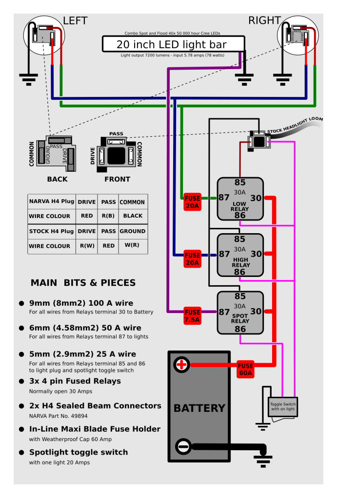 I know this may be a newbie question but can this relay set up be used with a HID conversion or would this relay set up be a waste of time considering the HID conversion installation?
|
|
|
|
|
fordem
Joined: Mon Apr 19, 2010 11:30 pm Posts: 2648 Location: Georgetown, Guyana
Vehicle: JB420, APK416, A6G415, A6N415
|
Posted: Tue May 14, 2013 10:07 pm |
|
|
Apart from being totally incorrect for a Suzuki - yes - you could use that with HIDs - 50W HIDs pull as much current as halogens.
|
|
|
|
|
|


